Stereo Vision Introduction and Applications
The purpose of this Technical Application Note is to provide a brief introduction to stereo technology, a description of Teledyne FLIR stereo products, and some application examples.
Overview
Stereo vision is an imaging technique that can provide full field of view 3D measurements in an unstructured and dynamic environment. The foundation of stereo vision is similar to 3D perception in human vision and is based on triangulation of rays from multiple viewpoints. Each pixel in a digital camera image collects light that reaches the camera along a 3D ray. If a feature in the world can be identified as a pixel location in an image, we know that this feature lies on the 3D ray associated with that pixel. If we use multiple cameras, we can obtain multiple rays. The intersection of these rays is the 3D location of the feature.
In practice, the key problems to solve in stereo vision are:
- Identify which pixels in multiple images match the same world feature. This is known as the correspondence problem.
- Identify for each pixel in the image the corresponding ray in 3D space. This is known as the calibration problem, and requires accurate calibration of the camera optical parameters and physical location.

The correspondence problem is solved through image processing software. Depending on the application, the algorithm used may solve correspondences for only a sparse set of features in the image (feature-based algorithms), or attempt to find correspondences for every pixel in the image (dense stereo algorithms).
Camera calibration is done before using the stereo rig. For dense stereo algorithms, typically the images from the cameras must be remapped to an image that fits a pin-hole camera model. This remapped image is called the rectified image. For lenses with barrel distortion, straight lines in the world will appear curved in the image. In the rectified image, however, barrel distortion is removed and straight lines will appear straight.
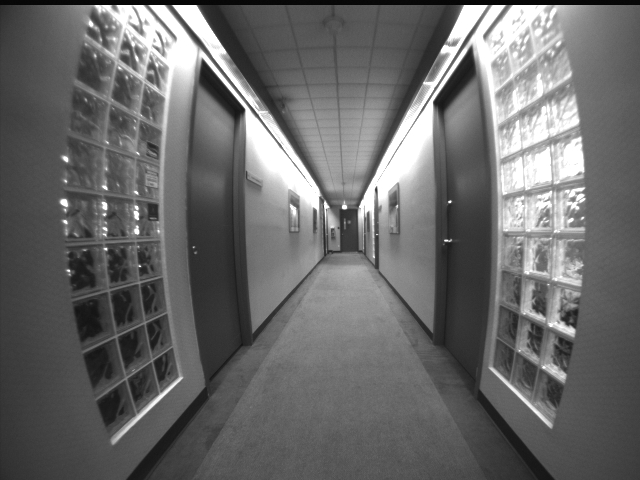
Figure 1: Wide-angle lens with barrel distortion
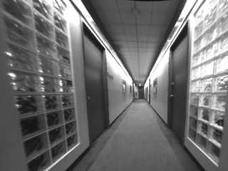
Figure 2: Rectified pin-hole model image
The accuracy of the 3D results of stereo matching depends upon many factors such as image texture, image resolution, lens focal length and the separation between cameras. Increase in camera separation or narrower field-of-view lenses improve the accuracy at long range. Higher image resolution increases the accuracy of the results but also may increase the processing time.
Stereo Cameras By Teledyne FLIR
We have made stereo vision practical for a variety of application areas by providing hardware and software packages that include complete stereo processing support – from image correction and alignment to dense correlation-based stereo mapping.
Bumblebee® stereo vision cameras are factory calibrated and come with a complete stereo vision software package called the Triclops™ SDK. The Bumblebee®2 uses two CCD image sensors to provide a balance between 3D data quality, processing speed, size and price. It can output 640x480 images at 48 FPS, or 1024x768 images at 20 FPS, via its IEEE-1394 (FireWire) interface. The Bumblebee® XB3 is a three-CCD multi-baseline stereo camera designed for improved flexibility and accuracy. It uses 1.3MP sensors with two baselines—12cm and 24cm—and can output 1280x960 images at 16 FPS via its 800Mb/s IEEE-1394b interface.
The Triclops Stereo SDK included with the Bumblebee2 and Bumbleebee XB3 supplies an assembly-optimized fast-correlation stereo core that performs fast Sum of Absolute Differences (SAD) stereo correlation. This method is known for its speed, simplicity and robustness, and generates dense disparity images. The Triclops SDK provides flexible access to all image stages in the stereo processing pipeline, making it ideal for custom stereo processing approaches.
Applications
Stereo vision technology is used in a variety of applications, including people tracking, mobile robotics navigation, and mining. It is also used in industrial automation and 3D machine vision applications to perform tasks such as bin picking, volume measurement, automotive part measurement and 3D object location and identification.
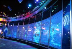
Stereo vision is also becoming the technology of choice for range sensing in mobile robotics navigation. The Bumblebee2 was selected as the primary range sensing method for the Princeton vehicle, “Prowler”, in the DARPA Urban Challenge, an autonomous vehicle research and development program that has robotic vehicles competing in a race in a complex urban environment.
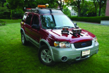
While other teams relied on a multitude of often extremely expensive sensors to guide their robotic cars through the course, Prowler used only three stereo video cameras to see and avoid obstacles. “We chose the Bumblebee cameras from FLIR because they provide a lot of quality data for low cost,” explains Gordon Franken, team spokesman for the Princeton team. “The cameras can see out to 60 meters and we were able to write just one obstacle detection algorithm and apply it to all the cameras.” Franken adds “We also like the cameras because they are passive sensors and don’t rely on beaming out laser or radar waves. In addition, the cameras wouldn’t be affected by stray laser or radar beams coming from a competing vehicle.”
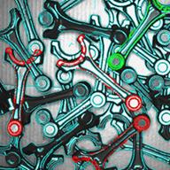
Random bin picking (RBP) is another application that benefits from the use of 3D vision. RBP requires a robot arm to locate and pick out specific items from a mixture of parts haphazardly piled in a container. Automation of this task is fraught with difficulties that are primarily sensing challenges. Parts need to be identified from any viewing angle, with overlap, occlusions, lighting variability and shadows making the problem more difficult. Where stereo vision provides the key advantage, however, is in further distinguishing the 3D environment of a part and determining whether a part is free to be grasped. This portion of the task is commonly solved with expensive laser scanners, to which stereo is a cost effective alternative.