Advancing Stereo Depth Perception in Industrial Automation
Introduction
Depth perception is essential for a wide range of warehouse robotic applications such as autonomous navigation, pick & place, inventory management, and more.
By combining depth perception with various types of 3D data (e.g. volumetric, point cloud, texture etc.) warehouse robots can navigate autonomously in complex environments, detect objects, avoid obstacles, pick up objects of interest, place them at specific locations, and optimize warehouse space usage to improve efficiency.
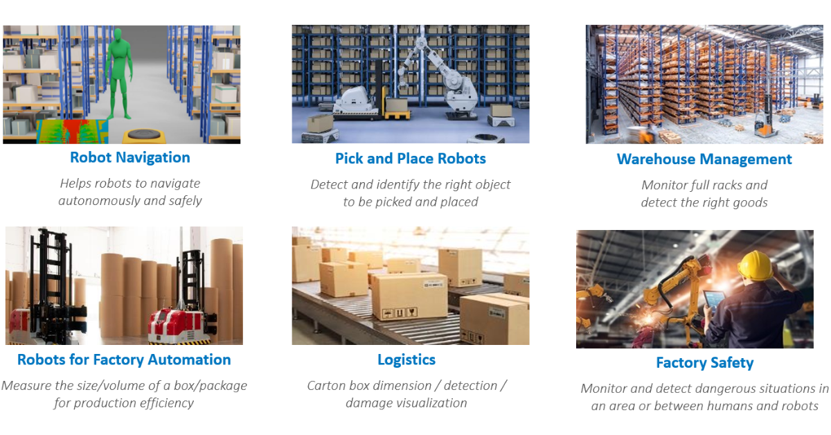
Figure 1. Example warehouse robotic applications.
3D Vision Technologies
3D sensors are a fundamental technology for measuring depth perception in real world scenarios. There are several common 3D vision technology options like stereo cameras, LiDAR, time-of-flight cameras, and laser triangulation.
The selection of 3D technology depends on the specific application and requirements because each technology delivers specific advantages. For example, LiDAR and laser triangulation technologies are not suitable for ruggedized applications due to the moving parts like rotating mirrors. Stereo cameras are a better fit for outdoor applications because they are not affected by sunlight interference. The cost of stereo cameras is typically lower than the other 3D sensor options.
Also, stereo cameras compute 3D data from images, and this requires higher computational power compared to the other technologies mentioned above. However, some stereo cameras offer on-board processing to offload the host data.
Moreover, for some applications, a color image is required for object recognition, and color point clouds can provide better situational awareness. Stereo cameras can provide color images and color point clouds whereas the other common 3D vision technologies require a separate color camera.
There is typically a trade-off between range and accuracy. For example, a long-range sensor has lower accuracy, while a short-range sensor has higher accuracy. Lidar offers the longest range, followed by stereo cameras, and then time-of-flight. Laser triangulation has the shortest range but higher accuracy. Longer range is needed for autonomous navigation and obstacle avoidance, while the medium range is needed for pick & place. Closer range is needed for object identification and inspection.
Stereo is suitable for most warehouse robotic applications. It offers flexible range with sufficient accuracy. It is relatively low-cost, easily ruggedized, and offers color image that is needed for object recognition.
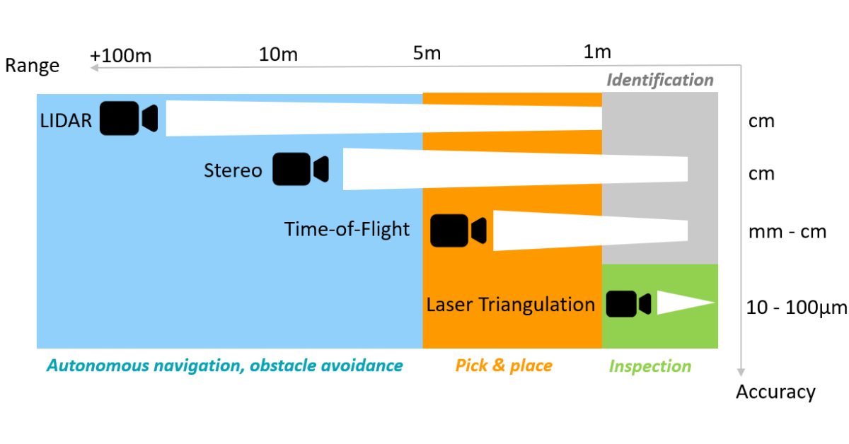
Figure 2. Balance between range and accuracy for various 3D vision technologies.
Stereo Imaging Overview
Stereo imaging is like 3D perception in human vision. Human pairs of eyes observing a scene from two viewpoints can infer the distance from the parallax (displacement in object location seen by the two different views).
Here are the key components of the stereo imaging pipeline. Before the system can be used, a one-time camera calibration must be performed as shown in the dashed line portion below.
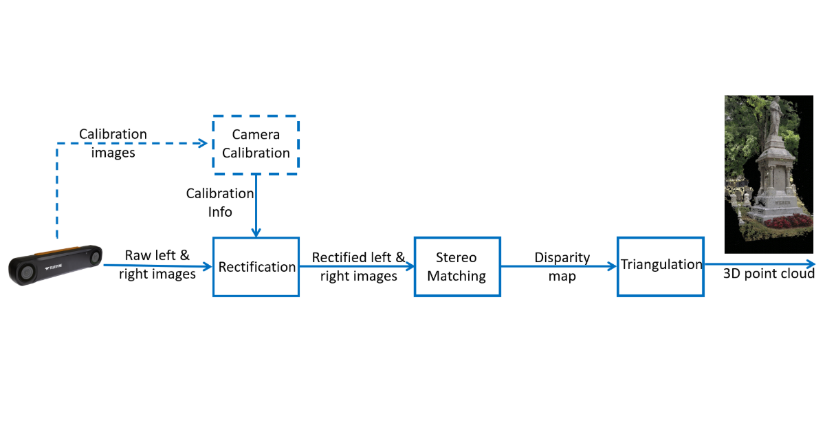
Figure 3. Stereo imaging pipeline overview.
For each frame, the camera first captures the raw left and right images, then the calibration information is used in the rectification step. The rectified images are passed to the stereo matching step to generate the disparity map. Finally, the triangulation step converts the disparity map into a 3D point cloud. Among these steps, stereo matching is the most computationally expensive. However, it can be optimized effectively as the processing is highly parallel.
The key design driver for a stereo camera is the 3D accuracy. The depth error is given by this formula: ΔZ = Z²/B⨍ Δd.
It depends on the following factors:
‘Z’ = Range
‘B’ = Baseline, that is the separation between the two cameras
‘⨍’ = Focal length in pixels, that is related to the camera field-of-view as well as the image resolution
Based on this formula, depth error increases quadratically with range. This is a key limitation of stereo cameras for long range operation. There are ways to reduce the error such as increasing the baseline, increasing the resolution, or decreasing the field-of-view.
Stereo Camera Industrial Applications
Warehouse robotics using Autonomous Mobile Robots (AMR)
Warehouses and factories can improve productivity and efficiency by automating material transportation with self-driving robotic vehicles. The AMRs perform SLAM (Simultaneous Localization and Mapping) by building a map of the environment and localizing themselves in the map at the same time. They plan routes to given destinations, detect obstacles (objects/people), and navigate around them.
The key benefits of AMRs include operation adaptability in different unstructured environments, and scalability. The warehouse will not require special infrastructure, staff remain safe, and a fleet of AMRs can operate together.
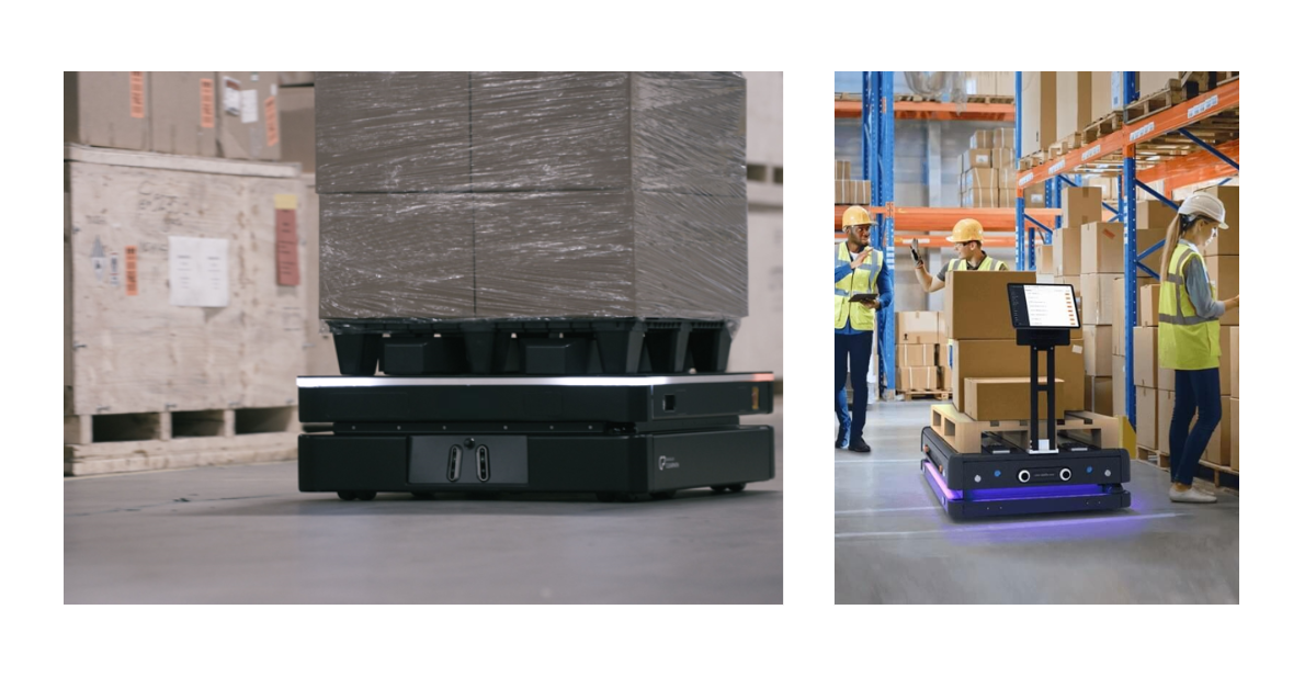
Figure 4. Stereo camera use case – Autonomous Mobile Robots (photos courtesy of OTTO and Gideon Brothers).
The following are the standard stereo camera feature/characteristic requirements for Autonomous Mobile Robots (AMR) applications:
- High frame rate
- Low latency
- Robust and reliable
- Calibration retention
- Wide field-of-view
- Longer working distance
- High dynamic range for indoor & outdoor use
Warehouse Robotics using Pick & Place Robots
Another common stereo camera warehouse robotics application is pick & place where robots pick up parts or items and place them in other locations. The key components for this application include a vision system to perceive the environment, a control system to process the data for decision making, and a robot arm with gripper or suction to manipulate the objects. The key benefits of pick & place robots compared to manual pick and place include better accuracy and consistency. They are flexible to accommodate changes in the environment, and they can handle repetitive tasks to free up human for more complex work, resulting in higher productivity and efficiency.
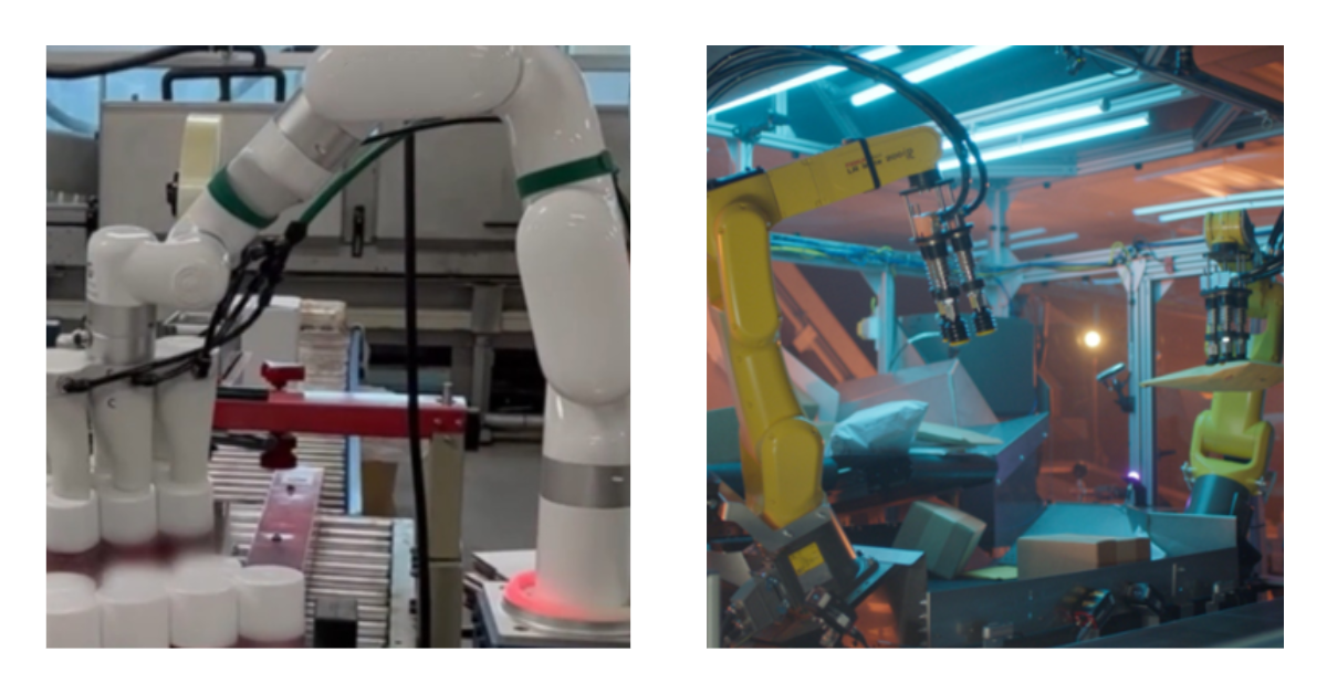
Figure 5. Stereo camera use case – Pick & Place Robots (photos courtesy of Taiga Robotics & Kindred/Ocado).
Pick & place robots can be used for a variety of applications such as assembly, palletization, depalletization, and bin picking. Using bin picking as an example, the objective is to remove randomly placed objects from a container. First, the vision system needs to recognize and locate an object and then compute its orientation so the gripper can grasp it properly. The control system then determines the robot trajectory, avoiding obstacles on its way. Finally, the robot picks up the object and places it at the destination.
The following are the standard stereo camera feature/characteristic requirements for pick & place robot applications:
- High accuracy
- Low latency
- Robust and reliable
- Calibration retention
- Dusty/humid industrial environment
- Different sizes of object require flexibility on field-of-view, and working distances
Real-World Challenges
We have identified several real-world challenges based on discussions with our customers. As the quality of a 3D point cloud depends on the image sensor data, typical machine vision challenges are applicable. For example, sufficient lighting should be provided to avoid long exposure time which may cause image blur. Common challenges regarding the 3D data include improving the 3D point cloud quality and reducing the latency in getting the 3D data. There are also practical stereo camera considerations after the system is deployed in the field.
Robot performance and decision making highly depend on the quality of the obtained 3D point cloud. There are various ways to improve the 3D point cloud:
- Higher sensor and stereo resolution produce more 3D points.
- Accuracy of the 3D points is improved with a wider baseline, higher resolution, and a narrower field-of-view.
- Denser and cleaner point clouds are obtained with a better stereo algorithm, but there is typically a trade-off between quality and speed.
- For low-texture scenes, point cloud density is increased by using a pattern projector.
- Noise in the point cloud is reduced by doing some post-processing such as median filter, speckle filter, temporal filter, etc.
Latency is the delay between an image being captured by the sensor in the camera and the transferring of the 3D data to the host. The benefits of low latency are faster decision making and more responsive interaction with the environment. Receiving the 3D data faster also allows more time for any subsequent AI processing. Here are the key factors that help reduce latency:
- With a more stream-lined camera architecture, pixels in a pipeline can be processed so there is no need to wait until the previous module finishes the whole image before starting the next module in the image pipeline.
- With faster stereo processing speed, the disparity image will be generated quicker and reduce latency.
- With higher transmission bandwidth, less time will be taken to transmit the data from the camera to the host, reducing latency.
After a system is deployed for use in production, it is crucial to continue to monitor performance over time. Here are some of the practical issues that can occur after deployment:
- If the camera is working intermittently or dropping connection frequently, which could be caused by unstable interface connection, consider a more stable industrial interface such as Ethernet rather than USB.
- If the camera fails due to the shock and vibration on the system, select a camera with high reliability, robustness, and IP rating.
- If the camera does fail and it cannot be replaced with the same model due to the product’s end-of-life, consider a product from a vendor that offers longer product lifecycle and support.
- If robot performance degrades over time, the stereo camera may need recalibration.
Calibration retention is critical for a stereo camera. A stereo camera that is not properly calibrated impacts the decision-making capabilities for the application. In Figure 6 below, the top row has a pair of sample stereo images and the disparity image for a well-calibrated stereo camera. On the bottom row, when the calibration has half a pixel row misalignment, the disparity image still looks reasonable, but as the misalignment increases, the disparity image quickly becomes worse which would result in fewer good 3D points and potentially more bad 3D points. Moreover, as the calibration error goes up, the stereo accuracy would get worse. It is important to select a stereo camera that will retain good calibration over time. Otherwise, it will need frequent re-calibration which is not practical after deployment in the field.
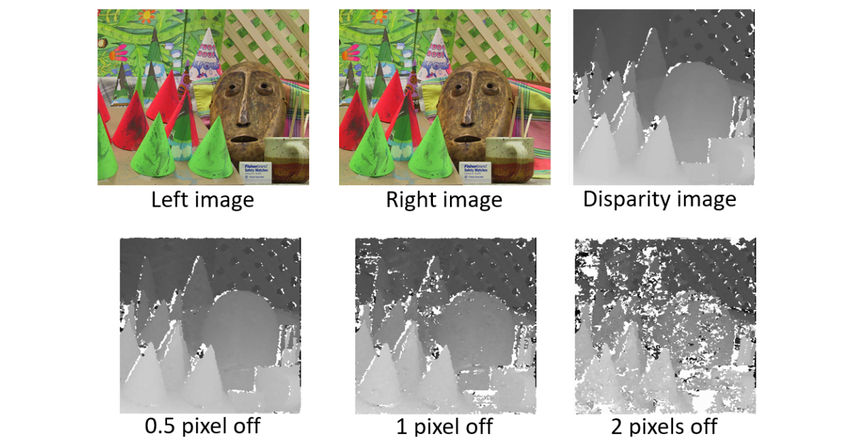
Figure 6. Importance of stereo camera calibration retention (Images source https://vision.middlebury.edu/stereo/data/).
Empowering Industrial Automation with Bumblebee X Stereo Camera
The next-generation Bumblebee® X stereo camera offers high resolution, exceptional accuracy, and advance on-board processing capability. In addition, its robust industrial design, IP67 rating, and 5 GigE interface ensure reliable integration into industrial environments.
Here are the key features of Bumblebee X:
- High resolution and high accuracy
- On-board processing with powerful stereo algorithm
- Long working distance with 24cm baseline
- Flexible field-of-view options (60, 80, and 105 degrees)
- High reliability and robustness with IP67 industrial design
- High bandwidth and low latency with 5 Gigabit Ethernet interface
- Calibration retention over time
- Compatible with external pattern projectors
- Extended product life cycle
- ROS (Robot Operating System) and GenICam support
- Easy-to-use and feature-rich SDK
Teledyne understands the critical needs of robotics professionals - fast data acquisition, low latency, and high 3D depth accuracy. Drawing on over 20 years of experience in calibration and stereo vision technologies, the Bumblebee X stereo camera is more than just a new stereo camera model. It is a continuation of excellence. Every capability that made the previous Bumblebee stereo camera innovative and reliable has been carefully preserved. The Bumblebee X delivers all this and with even more capability, equipped with the latest industrial grade 5GigE on-board processing stereo vision system.
Step into the future of robotics with a solution that combines cutting-edge technology, durability, and versatility. Maximize efficiency and minimize downtime while staying ahead in the competitive landscape. Choose Bumblebee X: Where innovation meets reliability.