10GigE Best Practices: Setting Up a Single-camera System

Best practices for host system configuration, cabling, and camera settings.
Whether you’re researching how to use 10GigE or are looking for tips on what you need to consider, this paper offers some best practices to help ensure the smooth set up and optimal performance of a single-camera 10GigE vision system. We list out our best practices for host system configuration, cabling, and camera settings.
Best practices for host system configuration
CPU
On a modern PC, reassembling ethernet packets into image data requires a small percentage of the CPU’s available processing power. However, most vision applications do far more than simply capture and store image data. To ensure you have enough processing power to analyze image data in real time, FLIR recommends a fourth generation Intel® Core™ i7 CPU or greater.
Mass storage
To stream to disk from an Oryx camera requires mass storage to keep up with the 10GigE interface. The popular SATA 3.0 mass storage interface has a maximum bandwidth of 6 GBit/sec. To stream at full bandwidth using SATA Hard Disk Drives or Solid State Drives (SSDs), a RAID array of two or more SATA 3.0 disks is required.
Most new motherboards support M.2 SSD. The M.2 standard uses a PCIe 2.0 x4 or PCIe 3.0 x4 interface that can theoretically provide enough bandwidth to keep pace with a 10GigE camera. Sequential write speed is still limited by flash memory technology. As of early 2018, the M.2 SSD with the fastest write speed is the Samsung NVMe SM951 series, which delivers a sequential write speed of 5.2 Gbit/sec.
Intel’s new Optane 3D XPoint™ memory can deliver write speeds up to 16Gbit/sec; however, the storage capacity of these devices is currently quite small.
Memory bandwidth
10 Gbit/sec is a lot of data; adequate memory bandwidth is essential for reliable operation of 10GigE cameras. A dual channel memory configuration ensures there is sufficient bandwidth to receive incoming packets, assemble them into images, and manipulate them in a vision application.

Fig. 1. Dual-channel memory delivers greater performance than a single-channel configuration
Rather than one large DIMM, use two smaller DIMMs that add up to the desired memory capacity. By installing system memory in a dual-channel configuration, memory bandwidth is doubled. Memory channels are color-coded on motherboards, simplifying setup. The speed and capacity of memory modules used in dual-channel configurations should match. Many memory manufacturers sell dual-channel kits.
Your system should automatically detect and enable a dual-channel memory configuration. However, it is recommended that this be confirmed and enabled in the BIOS, if necessary.

Fig 2. Examples of valid dual-channel memory configurations.
Systems that support triple and quad-channel configurations are also available. While the additional memory bandwidth of these systems will not improve the performance of 10GigE cameras, they may speed up memory and CPU-intensive vision processing applications. The current DDR4 memory standard is recommended, as it provides greater memory bandwidth than older technologies.
SDK
Using the latest version of Spinnaker is recommended and will ensure your system always has the latest features and performance enhancements.
Increasing the Stream Default Buffer Count creates more software buffers. This will improve system performance at the expense of consuming system memory. Buffer size is proportional to image size, so stream buffers for higher-resolution cameras will require more memory.
PCIe slot configuration
The PCIe slot that the Network Interface Card (NIC) is installed in can have a significant impact on system performance. Best practice is to plug the 10GigE NIC into the PCIe slot closest to the CPU. Not all motherboards can deliver full bandwidth to all PCIe slots. PCIe slots may share bandwidth with other peripherals such as USB ports or other PCIe slots. To determine which PCIe slots operate at full bandwidth, please see the detailed specifications in your motherboard’s user guide.

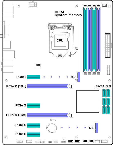
Fig 3. Common locations of PCIe, memory and storage connectors on an ATX form factor motherboard.
NIC settings
Jumbo frames reduce the load on the CPU by reducing the number of packets that must be reassembled into an image. NICs and switches used to connect 10GigE cameras should support 9K jumbo frames.
As 10GBASE-T is increasingly adopted for consumer products, a wide range of NICs has become available. Third-party testing has shown that not all 10GBASE-T NICs can deliver the full 10GigE bandwidth. The GE10-PCIE4XG202 sold by FLIR has been thoroughly tested and validated for use with our Oryx camera.
Best practices for cabling
Coiling ethernet cables that are longer than they need to be may result in connectivity issues, or the link between the camera and the host stepping down from 10GigE to GigE. This is due to interference between adjacent coils. The effect will be more prominent with CAT5e than CAT6A due to the additional shielding of CAT6A. Tight bends in CAT5e cables may also result in signal quality issues. RJ45 couplers should not be used.
For distances less than 30 meters, CAT5e will support a 10GigE link speed. For distances greater than 30m, CAT6A should be used. CAT6A cables have more robust shielding than CAT5e and may work better over short distances in environments prone to electromagnetic interference.
Best practices for FLIR camera settings
Oryx can be used in multi-camera systems with other Oryx 10GigE cameras or with GigE cameras like the FLIR Blackfly S.
To ensure reliable performance, the available interface bandwidth must be shared between the cameras. Exceeding the bandwidth of the interface between the switch and the host will result in packet loss and dropped frames.

Fig. 4. Setting the Device Link Throughput Limit to allocate interface bandwidth
The recommended method for setting camera bandwidth limits is with the Device Link Throughput Limit control. Once the Device Link Throughput is set, the camera will restrict the maximum frame rate to ensure it does not exceed its allocated bandwidth.

Fig. 5. Device link throughput setting in the Spinview GUI
In the SpinView GUI, the Device Link Throughput Limit setting can be found under the Device Control section in the feature browser, or using the search bar.