Setting Up Multiple GigE Cameras with FlyCapture2
Applicable Products
This application note is for users of Teledyne FLIR GigE cameras with the FlyCapture2 SDK.
For Teledyne FLIR GigE, 5GigE, and 10GigE cameras and the Spinnaker SDK please see Setting Up Multiple GigE Cameras with Spinnaker.
Preparing for Use
Before you use your GigE camera, we recommend that you are aware of the following resources:
Getting Started Manual for the camera—provides information on installing components and software needed to run the camera.
Technical Reference for the camera—provides information on the camera’s specifications, features and operations, as well as imaging and acquisition controls.
FlyCapture2 SDK—contains utilities to configure the camera (GigE Configurator and Driver Control GUI), update firmware and drivers, and check setup. As well, contains the FlyCapture2 API for use in creating your own applications.
Firmware updates—ensure you are using to most up-to-date firmware for the camera to take advantage of improvements and fixes.
Maximizing GigE Potential
Frame Buffer
All GigE cameras include a 32 MB frame buffer that can be used for temporary image storage. This may be useful in cases such as:
- Retransmission of an image is required due to data loss or corruption.
- Multiple camera systems where there is insufficient bandwidth to capture images in the desired configuration.
All images pass through the frame buffer mechanism.
GigE link layer IP
has implemented its own GigE link layer technology on an FPGA. This eliminates the dependency of a third party chip vendor and allows to continuously improve the camera and firmware to ensure maximum compatibility with third party hardware.
Image Filter Driver
To reduce GigE packet load on the CPU, provides the Image Filter Driver (pgrGigEm.inf). This driver operates between the camera and the Microsoft built-in UDP stack to filter out GigE vision stream protocol (GVSP) packets. The CPU does not process all the packets, and therefore is used less.
Configuring your GigE Camera
Configuring Drivers
Ensure you are using the best driver for your configuration. The Driver Control utility provided with FlyCapture2 allows you to verify which driver is in use and install a different driver if necessary.
GigE cameras can operate by communicating directly with the Microsoft UDP stack. However, it is recommended to use the Image Filter Driver in order to improve image streaming performance.
|
|
GigE cameras operating on Linux systems communicate directly with the drivers that come with Ubuntu distributions (i.e., no performance driver). |
To open the Driver Control utility:
Start Menu→All Programs→ Research→FlyCapture2→Utilities →DriverControlGUI
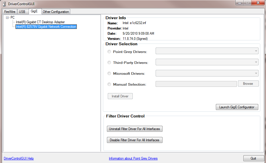
Figure 1. DriverControlGUI
(FlyCapture 2.3.1.7—Windows7, 32-bit)
Configuring Host Adapter and GigE Camera
The GigE Configurator is a utility that is installed with FlyCapture2 that allows you to control the configuration of your network adapter and GigE camera.
To open the GigE Configurator:
Start Menu →All Programs→ Research→FlyCapture2→Utilities→GigE Configurator
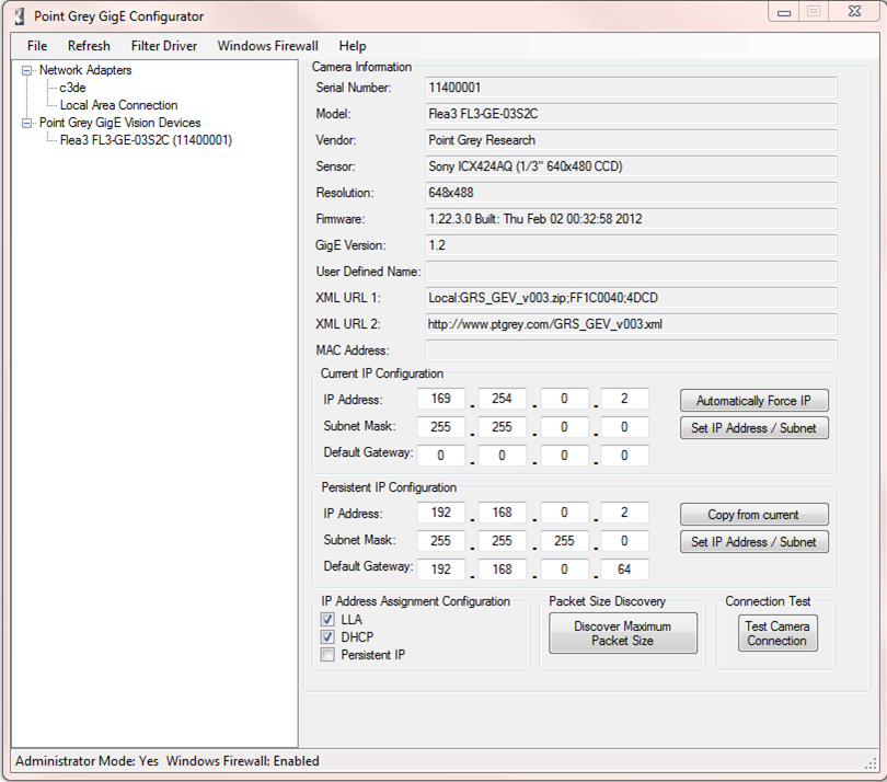
Figure 2. GigE Configurator
(FlyCapture2 v2.3.1.7—Windows7, 32-bit)
Note: The GigE Configurator can also be opened from the Driver Control utility.
The GigE Configurator lists your Network Adapters and your GigE devices and allows you to access the following:
- Adapter and device properties
- Manage IP addresses
- Link speed
- MTU (maximum transmission unit)
- Camera IP configuration options
- DHCP protocol
- Persistent IP
- Link-local address (LLA)
- Driver and firewall
- Enable/disable the image filter driver
- Enable/disable the Windows Firewall
As well, the GigE Configurator can be used to test the camera connection and discover the maximum packet size.
Setting the IP Address
Both the camera and the host adapter must have an IP address on the same subnet. This can be assigned in three ways:
Persistent—Both the adapter and the camera have a fixed IP address that will not change. Generally the address is within a closed network range of 192.168.X.X. The adapter and the camera must be on the same subnet.
|
|
Persistent IP addressing is recommended for multiple cameras on multiple ports. |
Dynamic (DHCP)—Both the camera and the adapter are set to automatically obtain an IP address. This means that the IP address will dynamically change (within a range) every time the camera or computer is restarted. It may take up to one minute for the IP address to resolve and the camera to enumerate.
Default (LLA)—Both the camera and the adapter use a default IP address from the link-local address block 169.254.x.x.
The camera assigns its current IP address in the following sequence:
- Persistent—Uses the defined IP address. If not available, then;
- DHCP—Attempts to find a dynamic IP address. If not available, then;
- LLA—Uses the default IP address.
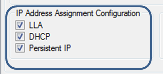
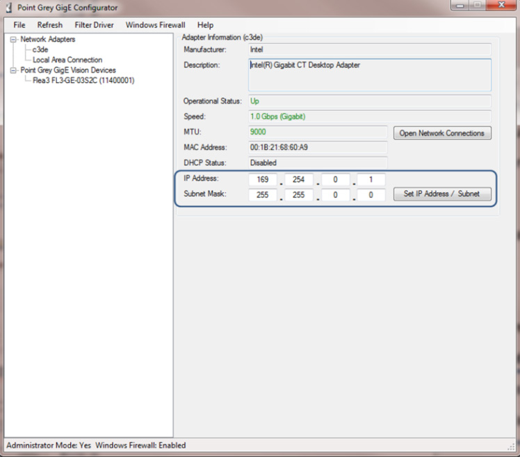
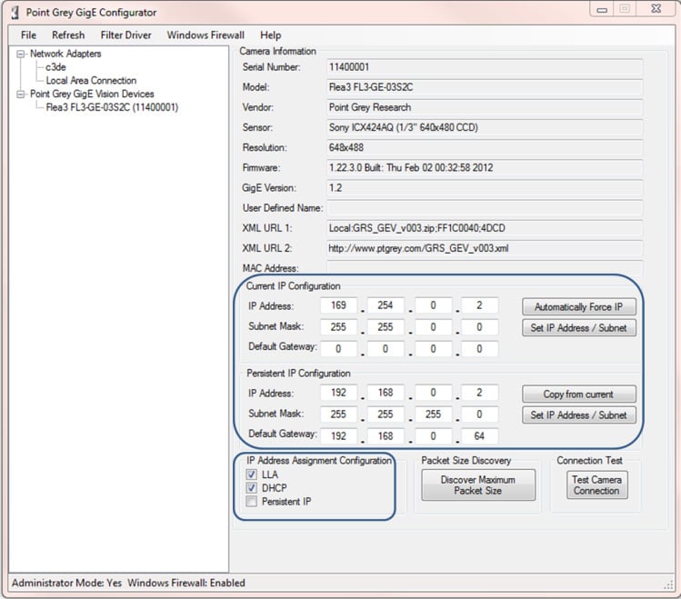
Figure 3. IP Address Assignment Configuration in GigE Configurator
(FlyCapture2 v2.3.1.7—Windows7, 32-bit)
You can use the GigE Configurator to set the IP address to both the adapter and the camera. LLA cannot be deselected as an option.
|
Network Adapter |
Camera |
|
|
|
|
Figure 4. IP Addressing in GigE Configurator |
|
Multiple Host Adapter
When setting up multiple cameras using multiple host adaptors. It is important to put each host adaptor on its own subnet.
For example:
| Subnet A | IP Address | Subnet Mask |
| Host Adaptor 1 | 192.168.100.1 | 255.255.255.0 |
| Camera 1 | 192.168.100.2 | 255.255.255.0 |
| Camera 2 | 192.168.100.3 | 255.255.255.0 |
| Subnet B | IP Address | Subnet Mask |
| Host Adaptor 2 | 192.168.200.1 | 255.255.255.0 |
| Camera 3 | 192.168.200.2 | 255.255.255.0 |
| Camera 4 | 192.168.200.3 | 255.255.255.0 |
Auto Force IP
The GigE Configurator can automatically force an IP address refresh. This detects the IP address of the Network Interface card and automatically sets the camera’s IP address relative to the card.
The FlyCap2 demo program can be used to test your camera settings and verify operation. From the camera selection window, you can also automatically force an IP address refresh.
Bandwidth Allocation
The User Datagram Protocol (UDP) used by the GigE Vision standard provides no guaranteed transmission or fixed timing mechanism. Therefore, bandwidth must be managed by adjusting packet size and packet delay, based on desired resolution and frame rate.
Packet Size
Packet size influences the number of interrupts generated which affects CPU usage. The larger the packet size, the fewer the interrupts for the same amount of data. To minimize CPU usage, increase the packet size.
The upper limit depends on your host adapter, your Ethernet switches (if used), and the camera.
From the GigE Configurator with your adapter selected, click Open Network Connections to open the Windows Adapter Properties. Adjust the packet size of your host adapter to ~9000 (the standard jumbo packet size). If your adapter does not support such a large packet (or MTU) size, then you will experience slightly higher CPU usage.
From the GigE Configurator with your camera selected, click Discover Maximum Packet Size. This will test the network to see the maximum size that can be sent and received. Set your camera’s packet size to be less than or equal to this maximum.
Packet Delay
The Packet delay acts like a gap between packets during transmission. This delay allows the host to process the current packet before the arrival of the next one. When you increase the packet delay value from zero, you reduce the effective bandwidth assigned to the camera and thereby also reduce the possibility of dropped frames.
|
|
Increasing the packet delay is recommended when running multiple cameras through an Ethernet switch. |
Adjusting Packet Size and Packet Delay
Packet size and packet delay for the camera are configurable using the FlyCapture2 API or the FlyCap2 demo program.
To use the FlyCap2 demo program:
1. Start Menu→All Programs→ Research→FlyCapture→FlyCap2
|
|
You must close the GigE Configurator before opening FlyCap2. |
2. In the Camera Selection window, select your camera and click Configure Selected.
3. In the Camera Configuration window, click Custom Video Modes. An estimate of the camera’s bandwidth is provided.
4. The GigE Packet Size and Packet Delay parameters can be adjusted using a slider or number field. Click Apply.
|
|
Changing the video mode, pixel format, or region of interest, may require further adjustments to the packet size/packet delay. |
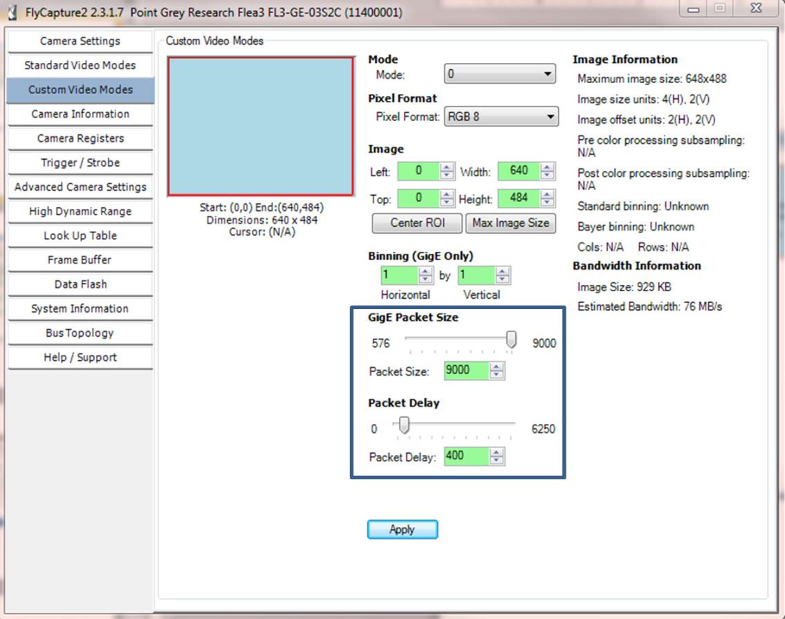
Figure 5. Packet Size and Packet Delay in the Camera Configuration window
(FlyCapture 2.3.1.7—Windows7, 32-bit)
Packet size for the host adapter is configurable through Windows Device Manager, accessible from the GigE Configurator. It is identified in the GigE Configurator as MTU (Maximum Transmission Unit) and in Device Manager as Jumbo Packet.
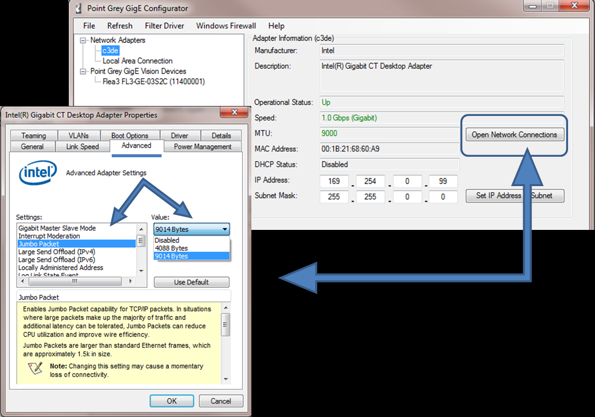
Figure 6. Setting Adapter Packet Size (MTU)
(FlyCapture2 v2.3.1.7—Windows7, 32-bit)
Calculating Required Bandwidth
The maximum bandwidth available is 125 MB. This includes image data, control data and image resends, which occur when frames are being dropped. Each image and each packet has a certain amount of overhead that will use some bandwidth. Therefore, when calculating your bandwidth requirements, you should not attempt to use the full maximum of 125 MB.
|
|
If the packet size and packet delay combination exceeds the available bandwidth, frames will be dropped. |
To calculate your bandwidth requirements:
- Determine your required resolution, frame rate, and pixel format (bytes per pixel)
Height x Width x Frame Rate x Bytes per Pixel = Bandwidth in MB
- As an example, for an image that is VGA, 82 FPS, Mono8:
640 (H) x 480 (W) x 82 (FPS) x 1 (BPP) = ~25 MB
FlyCap2 provides the estimated bandwidth on the Custom Video Modes tab.
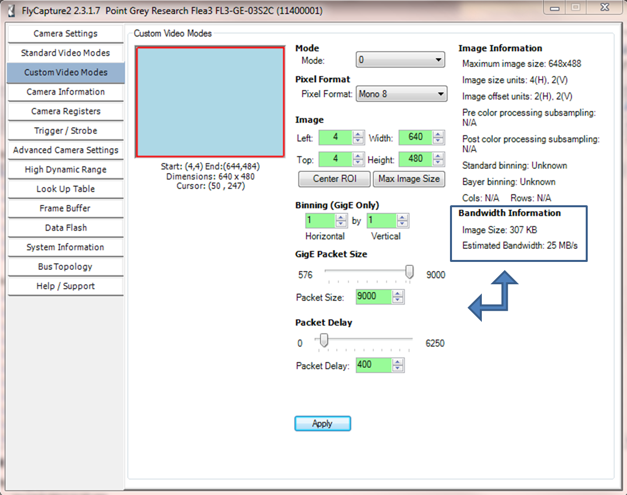
Figure 7. Estimated Bandwidth shown in the Camera Configuration window
(FlyCapture 2.3.1.7—Windows7, 32-bit)
|
|
If your version of FlyCap2 does not display Estimated Bandwidth, please download the latest version. |
Understanding your required bandwidth helps you determine what kind of configuration you need for setting up multiple cameras.
Once you have calculated your required bandwidth, you can allocate an amount to each camera by adjusting the packet size and packet delay. Allocating a specific amount to each camera helps to avoid dropped packets due to a data burst. You would do this in a set up with multiple cameras, or in a situation where the system bandwidth might be limited or shared due to hardware architecture.
Here are some packet size/packet delay combinations you can use with any image size, pixel format combination. Frame rate will be limited depending on total bandwidth.
| To allocate 25 MB~20% of bandwidth | To allocate 55 MB~ 45% of bandwidth |
| Packet Size = 9000Packet Delay = 5900 | Packet Size = 9000Packet Delay = 1800 |
| Packet Size = 1400Packet Delay = 900 | Packet Size = 1400Packet Delay = 255 |
Setting up Multiple Cameras
There are two methods of setting up multiple cameras.
Single camera connected directly to a single Ethernet Port

Figure 8. Single camera connected directly to a host adaptor
System Description
| Component | Description |
| CPU | Intel Core i3-2100 |
| Motherboard | Intel BLH6710H.86A |
| RAM | 2GB |
| Network adapter | Intel PRO 1000 PCIe Card (ACC-01-1100) |
| Cabling | Cat5e |
| Operating system | Windows 7 x86 |
| Driver | GigE Filter Driver 2.3.3.22 |
| Software | FlyCapture2 Release 2.3.2.14 x86 |
| Camera firmware | 1.24.3.0 |
| Camera Model | Pixel Format | Resolution | Frame Rate | Packet Size (Byte) | Packet Delay | Bandwidth (MBytes/s) |
| GS2-GE-50S5M-C | Mono16 | 2448 x 2048 | 11 | 9000 | 10 | 110 |
| Total Bandwidth | 110 MB/s | |||||
Multiple cameras connected to a single Ethernet Port through a switch
With a single Ethernet port, multiple cameras are connected to the host adapter via a switch. This set up combines the bandwidth from each camera onto a single cable; therefore, the sum of bandwidth used by all cameras cannot exceed 125 MB.
If you see frames being dropped on an individual camera, increase the packet delay for each camera to reduce the total bandwidth.
|
|
If possible, the switch should be configured to accept large packet sizes. You may need to adjust the camera’s packet size to suit the switch’s capabilities. |
Any method of IP addressing (Persistent, Dynamic, or LLA) can be used for this set up.
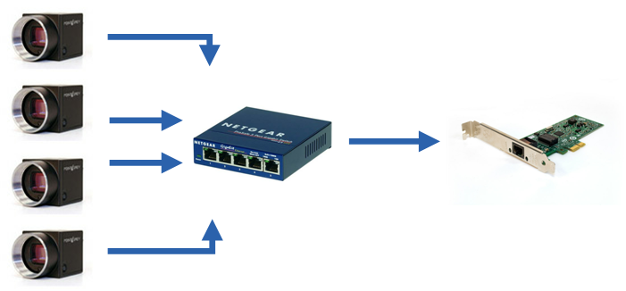
Figure 9. Multiple cameras connected to a host adaptor via switch
System Description
| Component | Description |
| CPU | Intel Core i3-2100 |
| Motherboard | Intel BLH6710H.86A |
| RAM | 2GB |
| Network adapter | Intel PRO 1000 PCIe Card (ACC-01-1100) |
| Network switch | Netgear GS105 5-Port Gigabit Switch |
| Cabling | Cat5e |
| Operating system | Windows 7 x86 |
| Driver | GigE Filter Driver 2.3.3.22 |
| Software | FlyCapture2 Release 2.3.2.14 x86 |
| Camera firmware | 1.24.3.0 |
Example A – Two cameras connected to a switch
| Camera Model | Pixel Format | Resolution | Frame Rate | Packet Size (Byte) | Packet Delay | Bandwidth (MBytes/s) |
| FL3-GE-03S1C-C | Raw16 | 648 x 488 | 62 | 1400 | 250 | 54 |
| FL3-GE-03S1M-C | Mono16 | 648 x 488 | 62 | 1400 | 250 | 54 |
| Total Bandwidth | 108 MB/s | |||||
Example B – Three cameras connected to a switch
| Camera Model | Pixel Format | Resolution | Frame Rate | Packet Size (Byte) | Packet Delay | Bandwidth (MBytes/s) |
| FL3-GE-03S1C-C | Raw8 | 648 x 488 | 55 | 1400 | 550 | 35 |
| FL3-GE-03S1C-C | Raw8 | 648 x 488 | 55 | 1400 | 550 | 35 |
| FL3-GE-03S1M-C | Mono8 | 648 x 488 | 55 | 1400 | 550 | 35 |
| Total Bandwidth | 105 MB/s | |||||
Example C – Four cameras connected to a switch
| Camera Model | Pixel Format | Resolution | Frame Rate | Packet Size (Byte) | Packet Delay | Bandwidth (MBytes/s) |
| FL3-GE-03S1C-C | Raw8 | 648 x 488 | 40 | 1400 | 850 | 25 |
| FL3-GE-03S1C-C | Raw8 | 648 x 488 | 40 | 1400 | 850 | 25 |
| FL3-GE-03S1M-C | Mono8 | 648 x 488 | 40 | 1400 | 850 | 25 |
| FL3-GE-03S1M-C | Mono8 | 648 x 488 | 40 | 1400 | 850 | 25 |
| Total Bandwidth | 100 MB/s | |||||
Multiple Ethernet Ports
With multiple Ethernet ports, multiple cameras are connected directly to a dedicated port. In this set up, each camera is able to use the full 125 MB bandwidth.
The host can have:
- One card with multiple ports
- Multiple cards each with a single port
- Multiple cards each with multiple ports
Persistent IP addressing is recommended for this set up. Each camera should have a unique IP address on the subnet of its port. Each port should be on a different subnet.
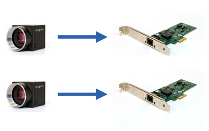
Figure 10. Two cameras each connected directly to a host adaptor
| Port | Camera Model | Pixel Format | Resolution | Frame Rate | Packet Size (Byte) | Packet Delay | Bandwidth (MBytes/s) |
| A | GS2-GE-50S5M-C | Mono16 | 2448 x 2048 | 10 | 9000 | 100 | 100 |
| B | FL3-GE-50S5M-C | Raw16 | 2448 x 2048 | 8 | 9000 | 300 | 80 |
| Total Bandwidth | 180 MB/s | ||||||
Cameras connected to multiple Ethernet ports and multiple switches
Using multiple Ethernet ports and multiple switches, you can increase the number of cameras connected on the host system. For this setup each Ethernet port will allow a maximum of 125MB bandwidth, which will be shared by the cameras that are connected to the port through a switch.
|
|
Jumbo packets need to be enabled for the switch to allow the camera to send larger image packets. |
Example A – Fourteen cameras connected to two Ethernet ports (7 cameras on each switch)
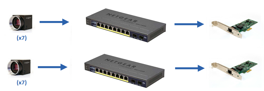
Figure 11. 14 cameras connected to two host adaptor via two 8 port switches
System Description
| Component | Description |
| CPU | Intel Core i3-530 |
| Motherboard | Intel Desktop Board HDH55HC |
| RAM | 2GB |
| Network adapter | Intel PRO 1000 PCIe Card (2x) (ACC-01-1100) |
| Network switch | Netgear GS110TP 8-Port Gigabit POE Smart Switch (2x) |
| Cabling | Cat5e |
| Operating system | Windows 7 x86 |
| Driver | GigE Filter Driver 2.3.3.54 |
| Software | FlyCapture2 Release Candidate 2.5.2.3 x86 |
| Camera firmware | 1.21.3.0 |
| Camera Model | Pixel Format | Resolution | Frame Rate | Packet Size (Byte) | Packet Delay | Bandwidth (MBytes/s) |
| BFLY-PGE-13E4C (3x) | Raw8 | 1280 x 1024 | 10.5 | 9000 | 62500 | 14 |
| BFLY-PGE-13E4M(4x) | Mono8 | 1280 x 1024 | 10.5 | 9000 | 62500 | 14 |
| BFLY-PGE-09S2C(4x) | Raw8 | 1288 x 728 | 14 | 9000 | 62500 | 14 |
| BFLY-PGE-05S2M | Mono8 | 808 x 608 | 29 | 9000 | 62500 | 14 |
| Total Bandwidth | 196 MB/s | |||||
Example B – Eighteen cameras connected to two Ethernet ports (7 and 11 cameras connected per switch)

Figure 12. 18 cameras connected to two host adaptor via 8 port switch and 52 port switch
System Description
| Component | Description |
| CPU | Intel Core i5-4750 |
| Motherboard | ASUS Z87-Deluxe |
| RAM | 8GB |
| Network adapter | Dual port Intel 82574L PCIe card (GIGE-PCIE-2P02) |
| Network switch | Netgear GS110TP 8-Port Gigabit POE Smart Switch,Cisco SG500-52P 52-Port Gigabit POE Managed Switch |
| Cabling | Cat5e |
| Operating system | Windows 7 x64 |
| Driver | GigE Filter Driver 2.3.3.61 |
| Software | FlyCapture2 Release 2.6.3.2 x64 |
| Camera firmware | 1.21.3.0 |
Seven cameras connected to Netgear GS110TP 8-Port Gigabit POE Smart Switch
| Camera Model | Pixel Format | Resolution | Frame Rate | Packet Size (Byte) | Packet Delay | Bandwidth (MBytes/s) |
| BFLY-PGE-13E4M | Mono8 | 1280 x 1024 | 12 | 9000 | 51000 | 17 |
| BFLY-PGE-05S2M | Mono8 | 808 x 608 | 34 | 9000 | 51000 | 17 |
| BFLY-PGE-05S2C | Raw8 | 808 x 608 | 34 | 9000 | 51000 | 17 |
| BFLY-PGE-09S2C(4x) | Raw8 | 1288 x 728 | 17 | 9000 | 51000 | 17 |
| Total Bandwidth | 119 MB/s | |||||
Eleven cameras connected to Cisco SG500-52P 52-Port Gigabit POE Managed Switch
| Camera Model | Pixel Format | Resolution | Frame Rate | Packet Size (Byte) | Packet Delay | Bandwidth (MBytes/s) |
| BFLY-PGE-13E4M(5x) | Mono8 | 1280 x 1024 | 7 | 6250 | 65535 | 10 |
| BFLY-PGE-13E4C(3x) | Raw8 | 1280 x 1024 | 7 | 6250 | 65535 | 10 |
| BFLY-PGE-05S2M(3x) | Mono8 | 808 x 608 | 19 | 6250 | 65535 | 10 |
| Total Bandwidth | 110 MB/s | |||||
Troubleshooting
Solving Enumeration Problems
If your camera is not showing up as a device consider the following:
Is the camera powered?
- Check that the camera LED is on
- Power is provided via GPIO on Flea3 and Grasshopper2; power is provided via PoE or GPIO on Zebra2 and Blackfly
Is there an IP conflict?
- Ensure the camera is using a unique IP address
- The camera and host adapter must be on the same subnet
Is the firewall blocking FlyCapture?
- Add FlyCap2 to your firewall program’s exceptions list or disable the firewall
Is other network traffic blocking your camera?
- Use a dedicated adapter for the camera and a separate adapter for the Internet or other devices
Is GigE enumeration enabled?
- Use the Registry Control utility to enable enumeration
Start Menu→All Programs→ Research→FlyCapture→Utilities→Registry Control
Is your camera showing up as “BAD” in the GigE Configurator?
This is usually caused by unmatched subnet address between the camera and the network adapter.
- Auto-force IP and Refresh
or
- Manually change the IP address of the camera to match the subnet of the adapter
Eliminating Image Consistency Errors
Image consistency errors are often caused by dropped packets. Ethernet is asynchronous in nature and capable of bursting data to peak bandwidth. A sudden burst in data transfer can create a packet collision and lead to image consistency errors.
If you’re experiencing image consistency errors, consider the following:
Is the correct driver installed?
- Install ’s image filter driver to reduce the packet load on the CPU.
Are all network components able to handle the packet size?
- In GigE Configurator, click the Discover Maximum Packet Size button to view the maximum size the network can handle.
- Use FlyCap2 to set camera’s packet size to be equal to or less than the maximum packet size.
- The packet size for the host adapter can be increased from the device manager.
- Ensure any switches in the network are also able to handle the packet size.
Is the packet delay too low?
- Increase the packet delay to slow down the average camera transfer rate. This can help with slower networks, less capable host computers, or for multiple cameras.
Is the computer able to handle the data?
- Free up system resources by ending unnecessary programs or processes.

