USB 3.1: Improvements over USB 2.0
Article Breakdown:
-
- WHAT IS USB 3.1
- BANDWIDTH IMPROVEMENT
- POWER DELIVERY AND MANAGEMENT
- CONNECTOR AND CABLING
- COMMUNICATION AND IMAGE TRANSFER
- SYSTEM AND SOFTWARE SUPPORT
- FUTURE OF USB 3.1
The Universal Serial Bus is one of the most common digital interfaces found today. SuperSpeed USB, also known as USB 3.1, is the next generation of the popular plug and play Universal Serial Bus interface specification. The USB 3.1 specification is drafted by the USB Implementer's Forum (USB-IF).
USB 3.1 brings new improvements to the interface as well as new challenges. These improvements and challenges are summarized in the table below. This whitepaper will discuss what these improvements and challenges are and how this has been reflected on USB 3.1 cameras.

SuperSpeed USB 3.1 Logo
| Improvements | Challenges |
|
|
Bandwidth
Improvements
USB 3.1 has improved upon the bulk data transfer mechanism of USB. Under ideal conditions, bulk transfer allows greater throughput compared to isochronous transfers. Real world measurement shows that the effective bandwidth available via the bulk transfer method is around 400 MByte/s; approximately 10 times that of USB 2.0. This important transfer mechanism has enabled machine vision camera vendor to build high throughput USB 3.1 cameras. This has created significant cost saving opportunities for integrators as well as improving the overall system speed and efficiency. Users can now use fewer cameras while still covering the same imaging area with large resolution USB 3.1 cameras. The higher bandwidth also allows for faster frame rate, increasing the performance of the system. For example, a system using four 0.3 MP, 30 fps USB 2.0 cameras can now be replaced by a single USB 3.1 camera running at 1080p and 30 fps for the same price while offering even more resolution.
The higher bandwidth has also allowed camera manufacturers to integrate high throughput sensors in to the camera. Users no longer have to turn to CameraLink cameras for high throughput sensors such as large resolution CMOS, or multi-tap CCD sensors.
In 2013, the USB 3.1 Promoter Group announced plans to enhance existing USB 3.1 performance by introducing a 10 Gbps USB 3.1 specification. The new specifications will double the existing USB 3.1 data rate while maintaining backwards compatibility.

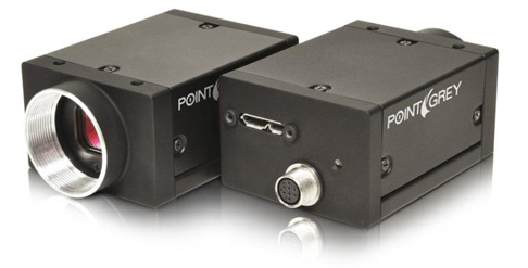
Grasshopper3 USB 3.1 featuring 2.8 MP - 9.2 MP Sony CCD sensors
Challenges
As the data bandwidth scales up, the host processing power must also scale up to handle the incoming data. Users may need to slow down the USB 3.1 camera when running on an older system.
Power Delivery and Management
Improvements
USB 3.1 has been designed to reduce power consumption while increasing its capacity to support and deliver more power. The introduction of USB Battery Charging 1.2 specification allows up to 7.5W of power to be supplied to USB 3.1 devices. USB 3.1 also offers an improved mechanism for entering and exiting low-power states, depending on whether a device is active or not, and eliminates power-consuming polling.
Challenges
USB 2.0 delivers only 2.5W of power. Since USB 3.1 cameras draws more power, backwards compatibility with USB 2.0 becomes more challenging. Some USB 3.1 cameras may be able to operate at a slower frame rate on a USB 2.0 bus and use less than 2.5W of power, while cameras with higher power draw may not work on USB 2.0 at all.

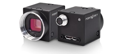
Flea3 USB 3.1 with max power consumption of 3W
Connectors and Cabling
Improvements
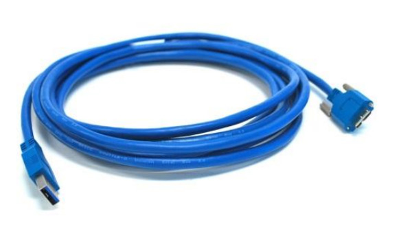
The physical difference between USB 2.0 and USB 3.1 is the number of wire connections. This new topology greatly improves bus utilization resulting in improved system throughput. USB 2.0 uses four wires which supports half-duplex communication. In this architecture, a single bi-directional data pipe is used where data only flows in one direction at any given time. In comparison, USB 3.1 adds five wires for a total of nine wires and utilizes a unicast dual-simplex data interface that allows for two uni-directional data pipes, with each pipe handling communication for a single direction. As part of the USB3 Vision specification, a Micro-B screw locking mechanism has also been standardized, increasing the reliability of USB 3.1 cameras in demanding industrial environments.

Challenges
USB 3.1 cabling and connector quality becomes ever so important when transferring at such a high data rate. This also makes it more difficult to make longer cables. Even though USB 3.1 specification does not specify a maximum cable length, Point Grey’s testing has found that passive copper cables are more reliable when the length is 5m or less. The distance between the USB 3.1 controller and cable connector in the host and camera side respectively will also influence maximum cable length between the host and camera. Point Grey has learned that some laptops for instance are limited to 3 meter cable lengths due to the trace length layout between the USB 3.1 controller and connector in the laptop.
Cable manufacturers are overcoming this challenge by extending cable distances using other mediums such as active copper cabling and fiber optics cables.
Communication and Image Transfer
Improvements
USB 2.0 employs a communication architecture where the data transaction must be initiated by the host. The host will frequently poll the device and ask for data, and the device may only transmit the data once it has been requested by the host. The high polling frequency not only increases power consumption, it also increases CPU usage and transmission latency because the data can only be transmitted when the device is polled by the host. USB 3.1 improves upon this communication model and reduces transmission latency by minimizing polling, lowering CPU usage, and allowing devices to transmit data as soon as it is ready.

Several improvements have been made in the USB 3.1 camera front when compared to USB 2.0 cameras. Many USB 3.1 cameras are incorporating frame buffer technology to improve data communication and reduce image corruption. The addition of a frame buffer allows the camera to utilize the error correction built in to bulk transfer and retransmit the corrupt data packets. Although error correction is also available with bulk transfer in USB 2.0, the lack of a frame buffer in USB 2.0 camera limited the amount of packet retransmission that the camera can do.
Challenges
Different camera vendors have chosen different ways to implement a USB 3.1 device controller onboard the camera. Some vendors have chosen to use a third party USB 3.1 device controller such as the Cypress FX3, integrating the controller with a sensor and creating a USB 3.1 camera. This speeds up the development of the camera and reduces the time to market of the product. However this limits the camera vendor’s ability to modify the device controller and delays USB 3.1 related fixes and improvements to the end customer. Teledyne FLIR has developed its own device controller on an FPGA on board the camera, as well as our very own device driver. This gives us full control over the imaging pipeline, allowing us to deliver features and improvements to customers much quicker.
Without a frame buffer acting as a cushion between the camera and the host system, cameras may suffer from dropped data when the host system cannot process the camera data fast enough, reducing the effective throughput of the camera.
System and Software Support
Improvements
Both Intel and AMD have been shipping their latest chipsets with native USB 3.1 support. Users using these chipsets will not have to purchase additional hardware to enable USB 3.1 in their system. Major operating systems such as Windows 8, Mac OS X and Ubuntu 12.10 all provide native USB 3.1 support as well. This means no additional third party driver will be required for the operating system to support USB 3.1 ports. This increases the usability of USB 3.1 technology and makes deployment easier.
Several machine vision standards exist today for popular interfaces such as IIDC for FireWire, and GigE Vision for Ethernet. The standards provide a common way to access and control machine vision cameras, increasing the ease of use, and allowing interoperability between different hardware and software vendor. As a next generation digital interface, it is important for USB 3.1 to have a similar protocol in order for it to be adopted by the machine vision industry. While no camera control standard exists for USB 2.0 cameras, a new standard called USB3 Vision has been ratified in 2013 for USB 3.1 cameras. USB3 Vision builds upon the popular GeniCam standard and defines USB 3.1 related requirements, device identification and control interfaces, data streaming mechanisms, mechanical requirements, and testing frameworks.
Future of USB 3.1
As a new technology, there are still challenges USB 3.1 must overcome as it becomes more mature. However, improvements such as higher bandwidth, enhanced power delivery, and better communications have convinced many users to adopt the technology and migrate to USB 3.1 from USB 2.0. As the next generation digital interface, USB 3.1 is found on all current shipping system hardware and will become ubiquitous, reducing the cost of deployment.
With camera features such as USB3 Vision support and unique CMOS and CCD offerings, USB 3.1 cameras will continue to be a very exciting platform for users in various industry segments.